Dimensioning Sheet Metal Flat Pattern

New To Sheet Metal Looking For Feedback About Dimensioning Autodesk Community Inventor

New To Sheet Metal Looking For Feedback About Dimensioning Autodesk Community Inventor

How To Define The Mbd Data Of Sheet Metal Parts Engineers Rule

How To Define The Mbd Data Of Sheet Metal Parts Engineers Rule

Solidworks Sheet Metal Drawing Tutorial Bend Line Flat Pattern Unfolded Bend Table Punch Table Youtube

Solidworks Sheet Metal Drawing Tutorial Bend Line Flat Pattern Unfolded Bend Table Punch Table Youtube

Sheet Metal Layout Tip Dimension To Formed View Not Flat Pattern

Sheet Metal Layout Tip Dimension To Formed View Not Flat Pattern

What Happened To My Flat Pattern View Computer Aided Technology

What Happened To My Flat Pattern View Computer Aided Technology

Drawing The Inventor Flat Pattern

Drawing The Inventor Flat Pattern

Drawing The Inventor Flat Pattern

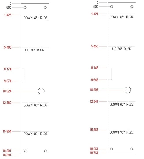
I think this is the better way because you can acquire your cutting length without a flat pattern by adding the inside lengths fold allowance.

Dimensioning sheet metal flat pattern.

Derive each body to a unique part file and then activate each part to flatten. Mathematically k factor value is equal to the ratio of position of neutral axis and sheet thickness. And also find you fold centers more easily. To know more about sheet metal k factor and flat length calculations.

In this article we will discuss sheetmetal bend deduction bend allowance k factor y factor and sheet metal flat pattern calculations. For example when sheet metal of length l is bend. Calculation flat pattern used as a template for cutting the pipe producing with wall thickness s 0. K factor in sheet metal bending is a constant used to calculate sheet metal flat length or flat pattern.

You can use this sheet metal flat pattern calculator to calculate this increase in length. After bending the total length a b is larger than length l. My boss dimensions from outside the flange walls and thinks. This is a common occurrence when manufacturers receive a sheet metal layout dimensioned in the flat pattern.

A part file can contain only one flat pattern. To convert a multi body. If you create multiple sheet metal bodies in a single part file the flat pattern command is disabled. When producing drawings of sheet metal components i dimension from inside the flange walls.

Solved Sheet Metal Drawings Dimension Problem Autodesk Community Inventor

Solved Sheet Metal Drawings Dimension Problem Autodesk Community Inventor

Standard For Dimensioning Sheet Metal Flat Patterns Induced Info

Standard For Dimensioning Sheet Metal Flat Patterns Induced Info

Solved Flat Pattern Dimensions In Parts List Again Autodesk Community Inventor

Solved Flat Pattern Dimensions In Parts List Again Autodesk Community Inventor

R11 Flat Pattern Vs Iv2008 Flat Pattern Autodesk Community Inventor

R11 Flat Pattern Vs Iv2008 Flat Pattern Autodesk Community Inventor

Source : pinterest.com